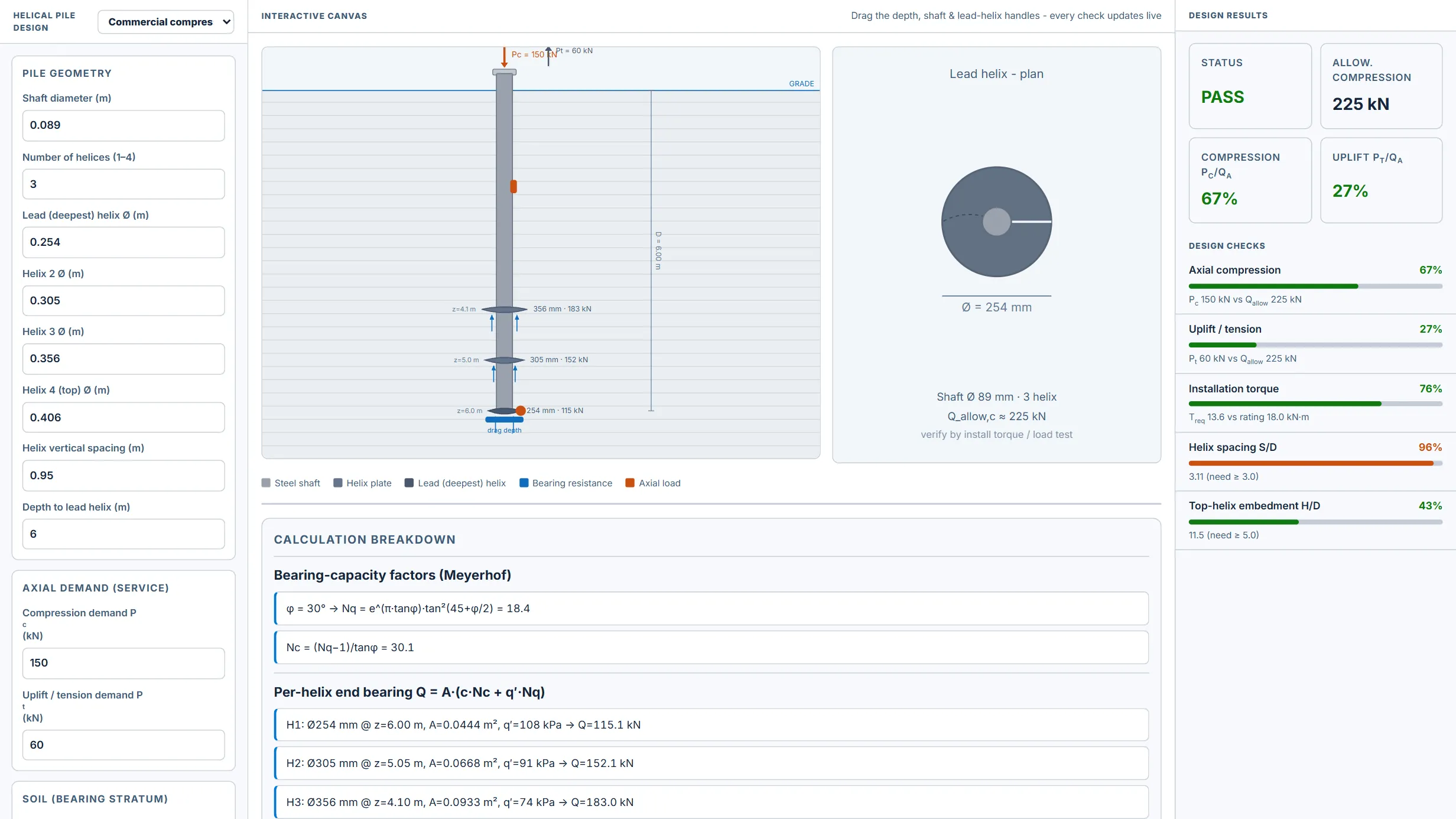
What it does
Preliminary axial design of a steel helical (screw) pile in compression and uplift using the individual-plate bearing method (Q_ult = ΣA·(c·Nc + q′·Nq) with Meyerhof bearing factors and effective overburden at each helix depth) cross-checked against the torque-correlation mechanical capacity (Q_ult = Kt·T_rating, the ICC-ES AC358 framework). Supports 1–4 helices with independent plate diameters and vertical spacing, an optional shaft side-resistance term (α-method clay / β-method sand), a water table for effective stress, and a global factor of safety. Computes the per-helix bearing contribution, the governing ultimate and allowable compression and uplift capacities, the installation torque required to develop the geotechnical capacity, a helix spacing S/D ≥ 3 individual-plate validity check, and a top-helix embedment H/D ≥ 5 deep-bearing check.
Includes an interactive elevation (drag the lead-helix depth, the shaft diameter, and the lead-helix plate diameter) showing the stacked helices, end-bearing reactions, and axial/uplift loads, a lead-helix plan view, and a capacity-by-helix bar chart, plus copy/CSV/JSON/print export.